|
|
|
|
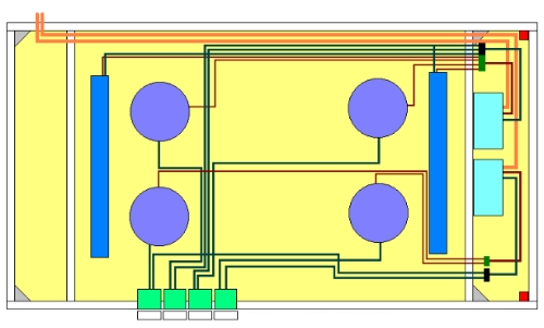
1. Using the lighting units as a template, measure out the circles they will fit into and cut excess material from melamine panel with jigsaw 2. Attach Halo recessed lighting units to melamine panel with several screws 3. Attach Flourescent units to other side with several screws and drill hole for routing the wire through the melamine panel 4. Attach the timers to the horizontal brace with screws, along with installing the oak trim to mount the end panel too 5. Using the dimmer switches as a guide, cut 4 mounting holes through the melamine front panel and secure dimmers with screws through the melamine panel. Install trim plates at this time. 6. Each Halo unit has a white, black, and copper wire coming from it. Run the black wire from each Halo lighting unit, to the black wire on it's respective dimmer switch. Secure with a 16AWG wire nut. Run a wire from the second black wire on the back of the dimmer switch to the timer unit. You should have 4 wires terminating at the timers at this point. One timer is used for daytime operation, one is for nightime. 7. Run the white wire from each Halo lighting unit to the timers. The wires from the rear Halo units go on the daytime timer. The wires from the front Halo units go on the nightime timer. 8. Run neutral wires (copper colored - one on each
halo unit) to the ground screw on their respective timers - this will
prevent short circuiting if it should ever occur. You should have
4 wires, one from each Halo unit. 9. Run a white, and a black wire from each of the Flourescents, to the daytime timer 10. Cut the plug from one end of each 16' cord and use it for power, one for each timer. Securely attach it to the inside frame of the overhead so some slack is maintained. 11. Thoroughly test your wiring configuration now, while changes can still be made to it. Check your dimmers for proper operation, check for any frayed insulation, loose wire nuts, etc. If all looks well, proceed to mount the unit by following the link below. One final note - I am NOT
an electrician. I can take no responsibility for anyone elses work.
This wiring arrangement has worked great from the start and operated
flawlessly to date. The timers provide consistent photo periods when
I'm not around, and the dimmers allow me to thermoregulate the enviroment
inside as the room temperature fluctuates. If you have concerns with
this section of the construction, hire an electrician. This is a guide
only due to liability issues
|
||
|
All comments and suggestions should be directed to
vze2372e@verizon.net |